Benefits of Multilayer Board
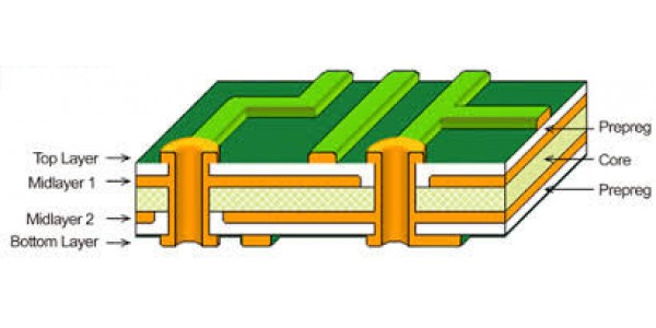
The first basic advantage of a multilayer board over a single
layer or a two layer board is that it provides more routing space. Experiences
PCB designers know how easy is it to drop down a via for power and ground nets.
It would not have been easy without defining power and ground planes. If a
board is not very dense and does not has BGA ICs, you can probably do with a 4
Layer PCB. If it has a BGA of pitch greater than or equal to 0.8 mm pitch you
can probably do it with 6 layers, assuming that the power nets are not many and
BGA is not very big. For BGAs of pitch 0.65 mm or lower and many power nets 8
layers or more may be required.
This is just a general guidance. We would like to minimize
the number of layers to keep the cost of PCB down. However, the extra layers in
the multilayer PCB fulfills some important High Speed PCB design requirements.
We must ensure that these requirements are fulfilled.

Power Plane for Impedance Requirements
Some high speed signals need their characteristic impedance
to have a certain specified value. For the characteristic impedance to have a
fixed value like 50 Ohms, it needs to refer to a metallic place (power or
ground) at a certain distance from it. The value of the characteristic
impedance depends upon the distance of the power plane from the trace (besides
trace width and relative permittivity). We must place the power plane beneath
the signal requiring a certain defined value for characteristic impedance.
Power Plane for Power Supply Requirement
The second important function of a power plane is that it
provides a return path for the power signals. Without power planes the power
signals would have to travel to the thin traces. The traces have inductance,
because of which fast returning current may induce noise in the power system.
The power and ground planes placed very close to each other provide a very low
impedance ac path for very high frequency noises on the power supply rail. This
helps mitigate the high frequency power supply noise issue in the board.
Tight Coupling and Crosstalk requirements
Keeping the high speed signals close to the power and ground
layers keeps the electromagnetic signals tightly coupled. Keeping high speed
signals in a stripline fulfills two important functions – first it reduces the
crosstalk. Secondly, it shields any potential radiation. It is therefore,
recommended that you rout your high speed signals in inner layers.
Power Plane and Stitching Capacitors
It is often happens that we have many power islands in a
single power plane. In this scenario we must be careful while routing the
controlled impedance traces which pass across the power islands junctions. We
must place the stitching capacitors at the junctions of the power islands. The
stitching capacitors provide ac return path and keeps the impedance constant
during the flight of the controlled impedance nets.


